LCD Modules can present textual information to user. It’s like a cheap “monitor” that you can hook in all of your gadgets. They come in various types. The most popular one can display 2 lines of 16 characters. These can be easily interfaced to MCU's, thanks to the API( Functions used to easily access the modules) we provide. LCD interfacing is just fun !
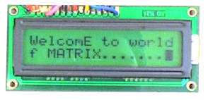 |
Fig: A 16x2 LCD Module |
PIN Configurations.
The lcd modules has 16 PINs for interfacing. The details are given below.|
LCD
Module Pin Configuration
|
|
1 VSS (GND Supply)
|
|
2 VCC (+5V)
|
|
3 VEE (Contrast Adjust)
|
4 RS
|
5 R/W
|
6 E
|
7 DB0
|
8 DB1
|
9 DB2
|
10 DB3
|
11 DB4
|
12 DB5
|
13 DB6
|
14 DB7
|
15 LED +
|
16 LED -
|
Connection with Board MINI.
The lcd module can be easily connected to the Board™ MINI the connection is as follows. |
Fig: Connection |
Adding LCD support to your project
To add LCD support to your C projects we have made a easy to use library. To use this library first create a new project in AVR Studio then copy the following files to your project folder. lcd.c lcd.h myutils.h from x:\xAPI\lcd-v20\ (where x:\ is your CD/DVD drive) then add them to your project by right clicking project view and selecting “Add Existing Source File(s)…” and then select the “lcd.c”. Similarly add “lcd.h” and “myutils.h” in Header Files section. Now you are ready to start coding LCD applications !!!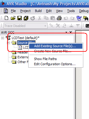 |
Fig: Adding files to projects. |
Programming.
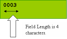
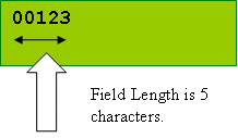
In your main C file include the file lcd.h as #include “lcd.h” then initialize the LCD subsystem using a call to LCDInit(LS_BLINK|LS_ULINE); the argument specify the type of cursor required the LS_BLINK gives a blinking cursor. LS_ULINE gives a underlined cursor. To write any text call LCDWriteString("Welcome"); To write any number call void LCDWriteInt(int val,unsigned int field_length); This will print a integer contained in “val” . The field length is the length of field in which the number is printed.For example LCDWriteInt(3,4); will print as follows
 |
 |
To goto any particular position on screen call.
| void LCDGotoXY(uint8_t x,uint8_t y); |
| LCDGotoXY(11,1); |
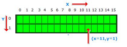 |
Fig: Cursor Positioning. |
Clearing the display
| LCDClear(); |
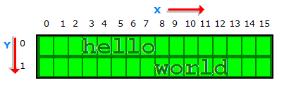
LCDWriteStringXY(x,y,msg);
____________________________
x,y : the location where to print “msg” msg : the message to print Ex: LCDWriteStringXY(3,0,”hello”); LCDWriteStringXY(8,1,”world”); Output:
|
LCDWriteIntXY(x,y,num,field_length); ____________________________________ x,y : the location where to print “num” num : the integer number to print field_length : the length of field (see LCDWriteInt() function above). |
Sample Program
#include <avr/io.h>
#include <util/delay.h>

#include "lcd.h"

void main()
{
   unsigned char i;

   //Initialize LCD module
   InitLCD(LS_BLINK|LS_ULINE);

   //Clear the screen
   LCDClear();

   //Simple string printing
   LCDWriteString("Congrats ");

   //A string on line 2
   LCDWriteStringXY(0,1,"Loading ");

   //Print some numbers
   for (i=0;i<99;i+=1)
   {
      LCDWriteIntXY(9,1,i,3);
      LCDWriteStringXY(12,1,"%");
      _delay_loop_2(0);
      _delay_loop_2(0);
      _delay_loop_2(0);
      _delay_loop_2(0);

   }

   //Clear the screen
   LCDClear();

   //Some more text

   LCDWriteString("Hello world");
   LCDWriteStringXY(0,1,"By YourName Here");    // <--- Write ur NAME HERE !!!!!!!!!!!

   //Wait
   for(i=0;i<100;i++) _delay_loop_2(0);

   //Some More ......
   LCDClear();
   LCDWriteString("    eXtreme");
   LCDWriteStringXY(0,1,"  Electronics");

}
Advance Use – Configuring Connections.
The library is designed to be fully customizable. If you want to connect the LCD module to some different i/o ports of the MCU then you can do so easily. You just have to modify the lcd.h file. Let’s see how. Open lcd.h and find a section “LCD Connections” it looks like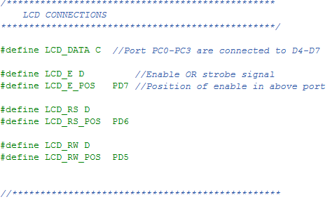 |
Fig: Configuring LCD Connection. |
PORTB.0->DATA4 PORTB.1->DATA5 PORTB.2->DATA6
PORTB.3->DATA7
The library uses advance 4-bit mode so DATA0-DATA-3 of LCD are not used, saving
4 MCU pins! Now set the port where you have connected LCD’s ‘E’ signal. In example
it is PORTD so #define LCD_E D Then specify to which PIN of PORTD it is connected,
this is done by #define LCD_E_POS PD6 So ‘E’ pin of LCD is connected to PORTD-6
In same way set RS and RW signals. And that’s all! So you saw how easy is to
customize the library. Downloads
Going Graphical ?
If you have more sophisticated display requirement then you may go for Graphical LCDs (GLCD) they can render graphics like Icons and bitmaps (images), support graphic primitives like line,circle, rectangle etc. Also they can draw text in different fonts and sizes. That means 100% fun! And they are cheap and very easy to get started (thanks to ProGFX.org). We have some beginners tutorials for it too. So why waiting? Go Graphical!What's next ??? |
| We will see what different Internal peripherals available on the AVR mcu and the methods of interface/communication from them. This will help you use internal peripheral like ADC,Timers,USARTs etc which will be covered in later tutorials. |