Most of the physical quantities around us are continuous. By
continuous we mean that the quantity can take any value between two
extreme. For example the atmospheric temperature can take any value
(within certain range). If an electrical quantity is made to vary
directly in proportion to this value (temperature etc)
then what we have is Analogue signal. Now we have we have brought a
physical quantity into electrical domain. The electrical quantity in
most case is voltage.To bring this quantity into digital domain we have
to convert this into digital form. For this a ADC or analog to digital
converter is needed. Most modern MCU
including AVRs has an ADC on chip.
An ADC converts an input voltage into a number. An ADC has a resolution.
A 10 Bit ADC has a range of 0-1023. (2^10=1024) The ADC also has a
Reference voltage(ARef). When input voltage is GND the output is 0 and
when input voltage is equal to ARef the output is 1023. So the input
range is 0-ARef and digital output is 0-1023.
Inbuilt ADC of AVR
Now you know the basics of ADC let us see how we can use the inbuilt ADC of
AVR MCU. The ADC is multiplexed with PORTA that means the ADC channels are shared
with PORTA. The ADC can be operated in single conversion and free running more.
In single conversion mode the ADC does the conversion and then stop. While in
free it is continuously converting. It does a conversion and then start next
conversion immediately after that.
ADC Prescaler.
The ADC needs a clock pulse to do its conversion. This clock generated by system
clock by dividing it to get smaller frequency. The ADC requires a frequency
between 50KHz to 200KHz. At higher frequency the conversion is fast while a
lower frequency the conversion is more accurate. As the system frequency can
be set to any value by the user (using internal or externals oscillators)( In
xBoard™ a 16MHz crystal is used).
So the Prescaler is provided to
produces acceptable frequency for ADC from any system clock frequency. System
clock can be divided by 2,4,16,32,64,128 by setting the Prescaler.
ADC Channels
The ADC in ATmega32 has 8 channels that means you can take samples from eight
different terminal. You can connect up to 8 different sensors and get their
values separately.
ADC Registers.
As you know the registers related to any particular peripheral module(like
ADC, Timer, USART etc.) provides the communication link between the CPU and
that peripheral. You configure the ADC according to need using these registers
and you also get the conversion result also using appropriate registers. The
ADC has only four registers.
- ADC Multiplexer Selection Register – ADMUX : For selecting
the reference voltage and the input channel.
- ADC Control and Status Register A – ADCSRA : As the name
says it has the status of ADC and is also use for controlling it.
- The ADC Data Register – ADCL and ADCH : The final result
of conversion is here.
(Please Read the Tutorial
"Internal
Peripherals of AVR" before using ADC of AVRs.)
Using the ADC.
In this sample we will setup and use the ADC in single conversion mode. We
will connect a LDR( light dependent resistor) which is a light sensor to input.
The result will be shown in LCD.
Initialization.
We have to configure the ADC by setting up ADMUX and ADCSRA registers. The
ADMUX has following bits.
ADMUX Register.
REFS1 REFS0 selects the reference voltage. See table below –
| REFS1 |
REFS0 |
Voltage Reference Selection |
| 0 |
0 |
ARef internal Vref Turned off |
| 0 |
1 |
AVCC |
| 1 |
0 |
Reserved |
| 1 |
1 |
Internal 2.56 Voltage Reference |
We will go for 2nd option, i.e. Our reference voltage will be Vcc(5v). So we
set
ADMUX=(1<<REFS0);
The ADCSRA Register.
We need to select division factor so as to get a acceptable frequency from
our 16Mhz clock. We select division factor as 128.So ADC clock frequency = 16000000/128
= 125000 = 125KHz (which is in range of 50KHz to 200KHz). So we set ADCSRA as
ADCSRA=(1<<ADEN)|(1<<ADPS2)|(ADPS1)|(ADPS0); //Enable ADC with Prescalar=Fcpu/128
Reading an analog value.
Now every thing is set up. We now write a routine that will ReadADC.
uint16_t ReadADC(uint8_t ch)
{
//Select ADC Channel ch must be 0-7
ch=ch&0b00000111;
ADMUX|=ch;
//Start Single conversion
ADCSRA|=(1<<ADSC);
//Wait for conversion to complete
while(!(ADCSRA & (1<<ADIF)));
//Clear ADIF by writing one to it
ADCSRA|=(1<<ADIF);
return(ADC);
}
We can call this function from any where from our code and simply need to pass
0-7 as for which channel we need to read.
Sample Code.
The following is complete code to Read Channel 0 and display its value on LCD.
#include <avr/io.h>
#include "lcd.h"
void InitADC()
{
ADMUX=(1<<REFS0); // For Aref=AVcc;
ADCSRA=(1<<ADEN)|(1<<ADPS2)|(1<<ADPS1)|(1<<ADPS0); //Rrescalar div factor =128
}
uint16_t ReadADC(uint8_t ch)
{
//Select ADC Channel ch must be 0-7
ch=ch&0b00000111;
ADMUX|=ch;
//Start Single conversion
ADCSRA|=(1<<ADSC);
//Wait for conversion to complete
while(!(ADCSRA & (1<<ADIF)));
//Clear ADIF by writing one to it
//Note you may be wondering why we have write one to clear it
//This is standard way of clearing bits in io as said in datasheets.
//The code writes '1' but it result in setting bit to '0' !!!
ADCSRA|=(1<<ADIF);
return(ADC);
}
void Wait()
{
uint8_t i;
for(i=0;i<20;i++)
_delay_loop_2(0);
}
void main()
{
uint16_t adc_result;
//Initialize LCD
LCDInit(LS_BLINK|LS_ULINE);
LCDClear();
//Initialize ADC
InitADC();
//Put some intro text into LCD
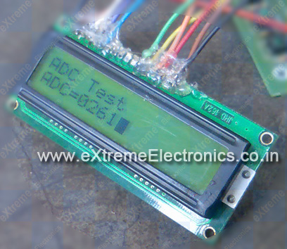
LCDWriteString("ADC Test");
LCDWriteStringXY(0,1,"ADC=");
while(1)
{
adc_result=ReadADC(0); // Read Analog value from channel-0
LCDWriteIntXY(4,1,adc_result,4); //Print the value in 4th column second line
Wait();
}
}
Hardware
|
|
Fig: LDR Connected to ADC of AVR
|
You have to connect a LDR (light dependant resistor) as shown above. After burning
the code on chip use a light source to throw some light on LDR, the ADC will show
a value between 0-1024 depending on light. For dark the value should be close
to 0 while for bright condition the value will become close to 1000.
|
|
Fig: Screenshot of ADC Test App.
|
|
Note:
More AVR ADC Applications
|
|
ADC Data On PC (Click to Read More ...)
|