Hello and welcome back to the discussion on the TIMERs in compare mode. In
the
last article we discussed the basics and the theory about using the timer
in compare mode. Now its time to write some practical code and run it in real
world. The project we are making is a simple time base which is very useful
for other project requiring accurate computation of time like a digital clock
or a timer that automatically switches devices at time set by user. You can
use it for any project after understanding the basics.
We will have three global variable which will hold the millisecond, second
and minutes of time elapsed. These variables are automatically updated by the
compare match ISR. Look at the figure below to get an idea how this is implemented.
|
|
Fig - Using AVR Timer to generate 1ms Time base.
|
|
Complete Code
#include <avr/io.h>
#include <avr/interrupt.h>

#include "lcd.h"

//Global variable for the clock system
volatile unsigned int   clock_millisecond=0;
volatile unsigned char  clock_second=0;

volatile unsigned char  clock_minute=0;

main()
{
   //Initialize the LCD Subsystem
   InitLCD(LS_BLINK);
   //Clear the display
   LCDClear();

   //Set up the timer1 as described in the
   //tutorial

   TCCR1B=(1<<WGM12)|(1<<CS11)|(1<<CS10);
   OCR1A=250;

   //Enable the Output Compare A interrupt
   TIMSK|=(1<<OCIE1A);


   LCDWriteStringXY(0,0,"Time Base Demo");
   LCDWriteStringXY(0,1,"  :   (MM:SS)");

   //Enable interrupts globally

   sei();

   //Continuasly display the time
   while(1)
   {
      LCDWriteIntXY(0,1,clock_minute,2);
      LCDWriteIntXY(3,1,clock_second,2);
      _delay_loop_2(0);
   }

}


//The output compate interrupt handler
//We set up the timer in such a way that
//this ISR is called exactly at 1ms interval
ISR(TIMER1_COMPA_vect)
{
   clock_millisecond++;
   if(clock_millisecond==1000)
   {
      clock_second++;
      clock_millisecond=0;
      if(clock_second==60)
      {
         clock_minute++;
         clock_second=0;
      }
   }
}
Hardware
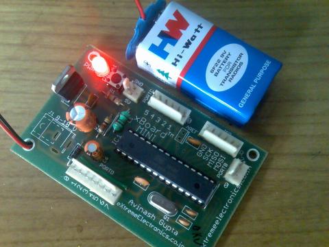
The hardware is ATmega8-16PU running at 16MHz with a LCD Connected to it.
I have used
xBoard MINI to make the prototype. You can also use your own ATmega8
board. To make a board in your own see
this.
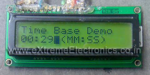
The output is displayed in a 16x2 character LCD module so please see the
LCD
interfacing tutorial for information about the connections and use.
I recommend you to first setup and test the LCD interfacing because it will
help you in many projects. If you have any problems setting it up please
post a comment here or use the
forum.eXtremeElectronics.co.in
|
|
Fig - xBoard MINI can be used to prototype many projects easily!
|
|
|
|
Fig - The output of above program in 16x2 LCD module.
|
|
Goodbye for now. Meet you in next tutorials !!! And don't forget to subscribe
to my feed via email to receive latest tutorials
direct in your
mail box.