Motor gives power to your MCU. Ya power to do physical works, for
example move your robot. So it is essential to know how to control a DC
motor effectively with a MCU. We can control a DC motor easily with
microcontrollers. We can start it, stop it or make it go either in
clockwise or anti clock wise direction. We can also control its speed
but it will be covered in latter tutorials.
DC Motor (Intermediate and Advance users can skip this)
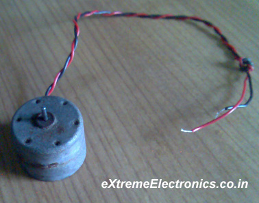
A DC motor is electromechanical device that converts electrical energy into mechanical
energy that can be used to do many useful works. It can produce mechanical movement
like moving the tray of CD/DVD drive in and out (you may like to try it out Go
to My Computer, right click the drive icon and click "Eject"). This shows how
software controls a motor. DC motors comes in various ratings like 6V and 12V.
It has two wires or pins. When connected with power supply the shaft rotates.
You can reverse the direction of rotation by reversing the polarity of input.
Control with MCUs
As the MCUs PORT are not powerful enough to drive DC motors directly so we need
some kind of drivers. A very easy and safe is to use popular L293D chips. It is
a 16 PIN chip. The pin configuration is as follows.
|
|
L293D Dual DC Motor Controller.
|
This chip is designed to control 2 DC motors. There are 2 INPUT and 2
OUTPUT PINs for each motors. The connections is as follows.
|
|
Fig: Motor Controller Using L293d chip.
|
The behavior of motor for various input conditions are as follows
| |
A
|
B
|
| Stop |
Low
|
Low
|
| Clockwise |
Low
|
High
|
| Anticlockwise |
High
|
Low
|
| Stop |
High
|
High
|
So you saw you just need to set appropriate levels at two PINs of the microcontroller
to control the motor. Since this chip controls two DC motors there are two more
output pins (output3 and output4) and two more input pins(input3 and input4).
The INPUT3 and INPUT4 controls second motor in the same way as listed above for
input A and B. There are also two ENABLE pins they must be high(+5v) for operation,
if they are pulled low(GND) motors will stop.The following program starts the
motor runs it one direction for some time and then reverses the direction.
#include <avr/io.h>
#include <util/delay.h>

void Wait()
{
   char i;
   for (i=0;i<100;i++)
      _delay_loop_2(0);
}

void main()
{
   //Setup port D pin 4,5 as output.
   DDRD=(1<<PD4)|(1<<PD5);

   while(1)
   {
      //Clock wise
      PORTD=0B00010000;
      Wait();

      //Anti clock wise
      PORTD=0B00100000;
      Wait();

      //Stop
      PORTD=0;
      Wait();
   }
}
Assembling.
|
Items Required.
|
|
DC Motor 12V
|
|
L293D chip
|
|
Breadboard.
|
|
Some wires
|
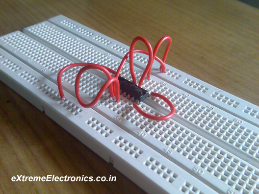
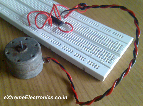
Insert the L293D chip into the breadboard. And connect as per the
circuit diagram. Now connect the DC motor. Then connect the 9V supply to
the breadboard this supply is used to run he motor. Also connect the 5V
supply to the breadboard this is the logical supply i.e. it defines a
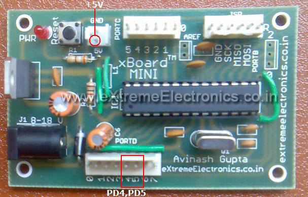
“HIGH’ or “1” is 5V. This 5V is available in the xBoard itself. Use a
2pin connector to access this. Then connect the PD4 and PD5 pins of the
MCU to the breadboard. These will provide signals to control the motor.
Use a 8 PIN connecter to get PD4 and PD5. Connect PD4 to ‘A’ and PD5 to
‘B’ Now burn the program into the MCU and power on the system. The motor
will rotate and will change directions after some times.
|
|
Fig: L293D chip on breadboard.
|
|
|
Fig: A motor Connected to l293d chip.
|
|
|
Fig: PD4,PD5,+5V and GND terminals on xBoard-MINI
|
Speed Control
The speed of DC motor can also be controlled with MCU. PWM or pulse
width modulation technique is used to digitally control speed of DC
motors. I will show you how that is done in later tutorials after I
introduce you with internal TIMERS of AVR because PWM is generated using
timers.