 |
Fig - Multiplexed Seven Segment Displays. |
 |
Fig - Multiplexed Seven Segment Displays. |
Programming
The actual programming will be covered in next tutorial. In this part we will simply see the steps involved. We will use the TIMER0 to refresh our displays. To learn about timer please see the previous tutorial. The timer will interrupt the CPU at predefined time interval an the CPU will switch to next display and display a digit there. An array variable uint8_t digits[3]; will hold the digits for the three displays what ever we need to display on the displays we store them there. So to display “911” on the display we store. digits[0]=1; digits[1]=1; digits[2]=9; The ISR of TIMER0 Overflow is as follows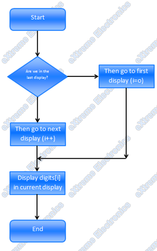
We set the TIMER0 prescaler as 256 so the sytem clock i.e. 16MHz is divided by 256 and the timer increment its value at 16000000/256 = 62500Hz i.e. 62.5KHz And timer overflows when its value changes from 255 to 0 so the frequency of Overflow is 62.5 KHz/ 256 = 244.140625 Hz As we switch display in each ISR the display of switching is 244.14 Hz since 3 switching are needed to completely draw a three digit number so the frequency of display update is 244.14/3= 81.38 Hz So we draw the complete digits approximately 81 times per second !!! This is too fast for our eyes to catch up so we see all three digits lit simultaneously. So friends this was the theory behind one of the most used techniques in MCU design world. You must have seen these Seven Segments used in weighing machines,PCOs and even currency counters in banks they all use this technique of Multiplexing the displays. Many microcontroller projects published in net of magazines uses multiplexed seven segment displays and this article will help you understand them. I said it all, now its your turn so all of you get ready for some typing because I need your comment on this post, simply say anything you think good or bad. While I write the next tutorial I will be heartily waiting for your comments.
|
WhatsNext ?
|
| We will write the code for this in AVR-GCC. Proceed to next part. Related |