Now you have the basic hardware tools, its time to setup the software
environment.The main software you will need are:
After downloading them install them in your computer. It is better to install
WinAVR in root of a drive like c:\winavr or d:\winavr. Also please install WinAVR
first then AVR Studio, this will let AVR Studio detect the compiler. Now you are
ready to write you first microcontroller program !!! In this tutorial, you will
learn the basic steps required for any microcontrollers based project. We will
write a basic “hello world” project, which is a simple LED blinker in MCU empire
to demonstrate these basic steps.
Step I Entering and compiling code.
Start “AVR Studio” from Start Menu->All programs->Atmel AVR
Tools-> AVR Studio 4
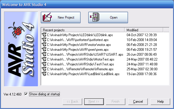
You will be presented with a Project wizard as shown below.
|
|
Fig - AVR Studio Project Wizard
|
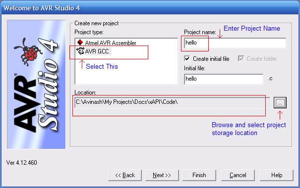
Select AVR GCC in Project type then enter a suitable project name say
“hello” and select a location in you hard disk. Then click next. Make
sure that “Create initial file” and “Create folder” option is checked.
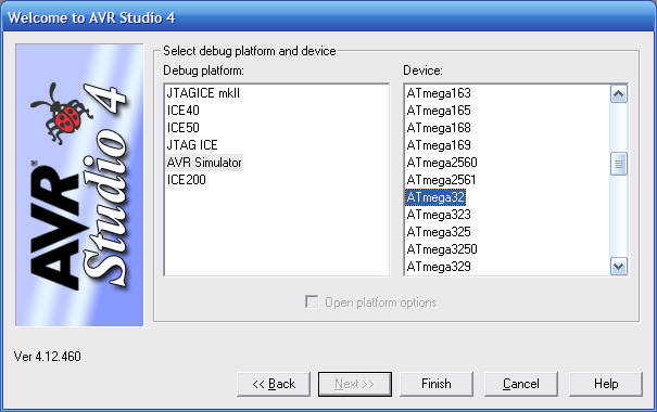
In this dialog box select AVR Simulator in “Debug Platform” list and
select the AVR MCU depending on the type of MCU installed on your
development board, in Device list. Click finish. After that you will be
presented with an Integrated Development Environment-IDE. As shown
below.
|
|
Fig - AVR Studio main window
|
| |
This IDE will help you in editing, modifying, and compile source
program. After a project is compiled it gives you a “.hex” file ready to
burn to your MCU. The main parts of the window are
-
Project Area – displays all the files source and header
in the current project. You can add and remove files by the context menu
of different groups like “source file” , “header files” etc. Double click
a file to open it in the editor.
-
Code Editor – Here you enter and edit the files.
- Message Area – Here AVR Studio will show errors and warning
generated by compile when it tries to compile a source file.
Now copy past or type the following code in the code editor.
#include <avr/io.h>
#include <util/delay.h>

void Wait()
{
   uint8_t i=0;
   for(;i<23;i++)
      _delay_loop_2(0);
}

void main()
{
   //Set PORTC0 as output

   DDRC=0b00000001;

   while(1)
   {
      //Set PC0=High(+5v)
      PORTC|=0b00000001;
      Wait();

      //Set PC0=Low(GND)
      PORTC&=0b11111110;
      Wait();
   }
}
If you don't understand the program don't worry, the next tutorial will teach
you how to
setup
and use general purpose IO ports in AVR.
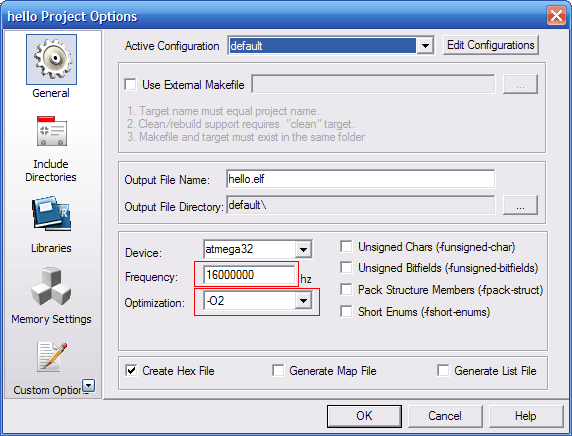
Go to
Project->Configuration Options to bring the Project
option dialog.
|
|
Fig - Setting CPU frequency and compiler optimization
|
| |
Enter the CPU frequency. If you are using xBoard™ or xBoard™ MINI enter
16Mhz i.e. 16000000. In addition, select optimization as -O2. Click ok.
Now you have entered the code now time to compile and build the project.
Press
F7 or select
Build->Build or click the toolbar button for
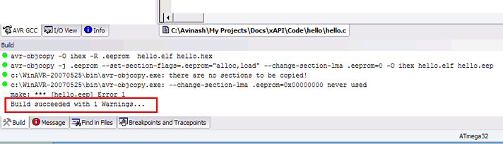
Build active configuration. If the code is error free AVR studio will show you the following message.
“Build succeed with 1 warning. Don’t worry about the one warning it is
due to the fact that ANSI standard suggest that return type of
main() must
be one, but for MCU platform there is no environment or operating
system that will receive this returned value. So return type of
main() is void.
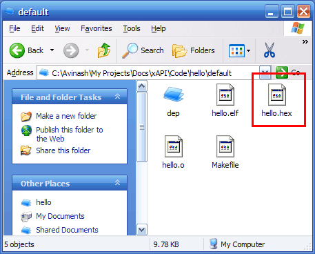
Now you have successfully compiled you first project, what you have got after compilation and build is
“.hex file”. You can find it in a folder named “default” in you project folder. It has same name as you project, in this case
“hello.hex”
|
|
Fig - Finding "hello.hex" file
|
| |
Step II Programming the MCU with “hello.hex”.
Now its time to burn this hex file to your MCU. To know how to burn the hex file
to you MCU refer to you programmers manual. You can use
eXtreme
electronics USB AVR Programmer to burn hex files to you mcu (see shop section).
Detailed procedure is given in “programmer” folder in its support CD.
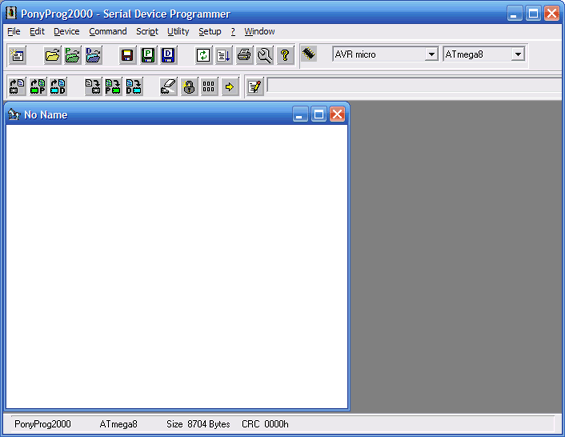
Programming Using PonyProg.
This is the programmer we made in the previous tutorial. Its use is
simple. Start Ponyprog, you will get a screen similar to this.
|
|
Fig - Ponyprog main window.
|
| |
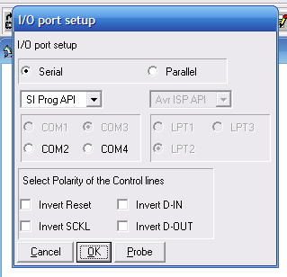
First, you need some setup. Go to menu setup->interface setup and make setting
like this.
Select the serial port in which your programmer is connected. Beware
there may be more that 1 available com port showing there and usually
only one is available outside the PC the rest are internal and may be
connected to your modem. So make sure you have selected a port that is
connected to your programmer and not to your modem.
Next, go to set up->calibration. Now you are done.
Connect the programmer you have made to you PCs serial port and connect
its ISP connector to the target you have made. Switch on the target.
The software is self explanatory with easy to use GUI in the top tool
bar there is a selection for type of chip you want to program. Select
“AVR Micro” and select the type of Micro( like ATmega8) in box next to
it.
- Select the hex file you want to program using the File->Open Program(FLASH)
file.
- Command->Erase.
- Command->Write Flash
- Command->Verify Program(FLASH)
- If every thing is correct, your MCU is programmed successfully.
- Disconnect programmer from the Target and switch it off.
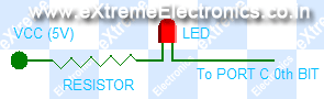
Step III Electrical Connections.
This is a very simple project you don’t need any complicated connection.You may
be using any of our development boards like
xBoard™,
xBoard™ MINI or simpler xCards™. You just need to figure out where is the
MCU ports (which is programmed to blink LED, in this case PORT C’S 0TH BIT) connector
on the board. They are clearly marked in the boards. After finding it, connect
the LED as follows to the MCU port .Or you can make your own target boards as
explained in previous tutorials. I am not showing all the connection here because
I have already shown in previous tutorials.
The VCC (5v) required is also available in the board and marked as “spare 5V”
or something like that. After all connections connect power supply (make sure
the polarity is correct) to the board and switch on. The power indicator LED
of board should glow and the LED connected to the MCU’s port should blink on
and off. Now you can relax and enjoy than light blinking with all that modern
sophisticated technology behind it and you first dedicated embedded program
doing all the magic.
Now go on with your imagination tweak the program, modify delay and switching
logic to get interesting patterns blinking. The limit is your imagination.
Note
|
| Note: For More information on using AVR studio see AVR GCC Plugin Help
in the Help Menu |