Seven segment displays are very common for electronic product to
display numerical output. Many common devices like calculators, watches,
electronic weighing scales,ovens etc use them. You must have also seen
lifts display the current floor numbers in seven segment displays. So in
this article I will show you how to use 7-Segment displays in your own
projects.
Fundamentals
A seven-segment display is so named because it is divided into seven different
segments that can be switched on or off. The different combination of these
segments switched on produces different English numbers. The display also has
a decimal point.
|
|
|
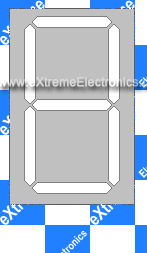
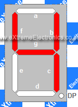
Fig: Seven Segment Display
|
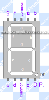
The figure shows a seven segment display and the names of the various segments.
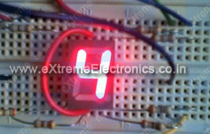
For example if you want to display number 4 then segments that will be ‘on’
are {f,g,b,c} while rest are ‘off’.Basically the seven segments are just LEDs.
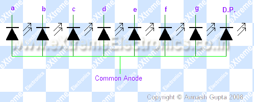
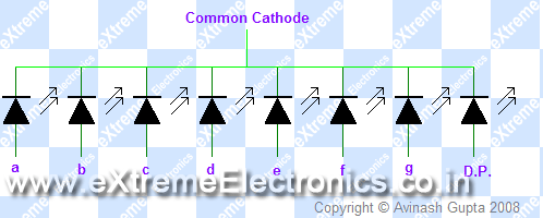
The one common end of all the leds are connected while the rest are available.
Depending on whether anode or cathode of all the leds are common they are
of two types.
1) Common anode 2)Common cathode
PIN Configuration
Now you know the basic of these displays, to use them you should know the pin
configuration of the commercially available displays. As you must have guessed
these displays should have nine pin( one for each segment + decimal point +common)
but the available modules have two pins for common. They are internally connected.
So they have total of 10 PINs.
|
|
|
Fig: A seven segment display
|
Interfacing with MCU
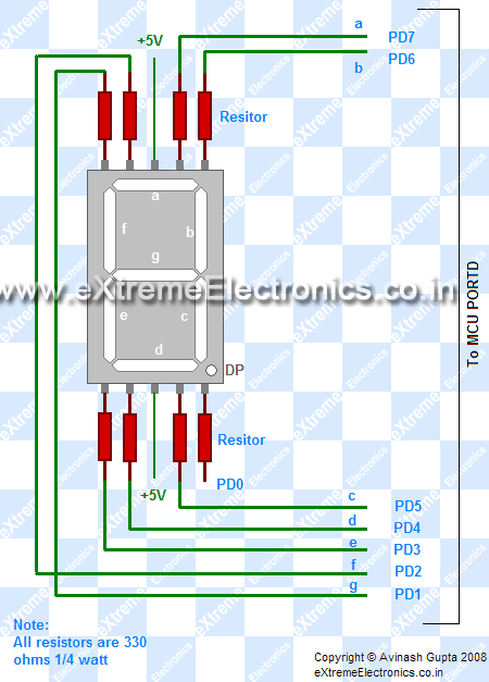
Interfacing these displays are same as interfacing LEDs with MCU. You need 7 MCU
port pins to control them. If you also want to control the decimal point you need
one extra pin. The connection is simple.
Here I have interfaced a common anode(+) 7 segment display with PORTD of AVR.If
you have made the “home made avr dev board” then you can easily connect this
to PORTD of the board by using 8PINconnectors. The segments will be "on"
when levels on the PORT is low, that is 0.
Programming
These displays are very easy to program in C. I am giving here a function, which
you may use to display digits in 7-segment display. The sample program uses the
function to continuously display digits from 0-9 and then repeating the sequence.
/*

A program to demonstrate the use of seven segment displays.

Hardware:
A single seven segment display connected to PORTD as

a->PD7
b->PD6
c->PD5
d->PD4

e->PD3
f->PD2
g->PD1
DP->PD0


*/

#include <avr/io.h>
#include <util/delay.h>

//Configurations

//**************
// Here you may cange the port in which you have connected the display
#define SEVEN_SEGMENT_PORT PORTD
#define SEVEN_SEGMENT_DDR DDRD


void SevenSegment(uint8_t n,uint8_t dp)
{
/*
This function writes a digit given by n to the display

the decimal point is displayed if dp=1

Note:
n must be less than 9
*/
   if(n<10)
   {
      switch (n)
      {
         case 0:
         SEVEN_SEGMENT_PORT=0b00000011;
         break;

         case 1:
         SEVEN_SEGMENT_PORT=0b10011111;
         break;

         case 2:
         SEVEN_SEGMENT_PORT=0b00100101;
         break;

         case 3:
         SEVEN_SEGMENT_PORT=0b00001101;
         break;

         case 4:
         SEVEN_SEGMENT_PORT=0b10011001;
         break;

         case 5:
         SEVEN_SEGMENT_PORT=0b01001001;
         break;

         case 6:
         SEVEN_SEGMENT_PORT=0b01000001;
         break;

         case 7:
         SEVEN_SEGMENT_PORT=0b00011111;
         break;

         case 8:
         SEVEN_SEGMENT_PORT=0b00000001;
         break;

         case 9:
         SEVEN_SEGMENT_PORT=0b00001001;
         break;
      }
      if(dp)
      {
         //if decimal point should be displayed

         //make 0th bit Low
         SEVEN_SEGMENT_PORT&=0b11111110;
      }
   }
   else
   {
      //This symbol on display tells that n was greater than 9
      //so display can't handle it

      SEVEN_SEGMENT_PORT=0b11111101;
   }
}


void Wait()
{
// An approx one second delay for  12Mhz CPU clock
   uint8_t i;
   for(i=0;i<46;i++)
   {
      _delay_loop_2(0);
   }
}


void main()
{
   //Setup
   SEVEN_SEGMENT_DDR=0xFF;    //All output
   SEVEN_SEGMENT_PORT=0xFF;   //All segments off

   uint8_t count=0;

   while(1)
   {
      SevenSegment(count,0);

      count++;
      if(count==10)
      {
         count=0;
      }

      Wait();
   }
}
