Wednesday, January 17, 2007

CGRAM and Character Building

►CGRAM and Character Building

As already explained, all character based LCD of type HD44780 has CGRAM area to create user defined patterns. For making custom patterns we need to write values to the CGRAM area defining which pixel to glow. These values are to be written in the CGRAM adress starting from 0x40. If you are wondering why it starts from 0x40? Then the answer is given below.


Bit 7 is 0 and Bit 6 is 1, due to which the CGRAM adress command starts from 0x40, where the address of CGRAM (Acg) starts from 0x00. CGRAM has a total of 64 Bytes. When you are using LCD as 5x8 dots in function set then you can define a total of 8 user defined patterns (1 Byte for each row and 8 rows for each pattern), where as when LCD is working in 5x10 dots, you can define 4 user defined patterns.

Lets take an of bulding a custom pattern. All we have to do is make a pixel-map of 7x5 and get the hex or decimal value or hex value for each row, bit value is 1 if pixel is glowing and bit value is 0 if pixel is off. The final 7 values are loaded to the CGRAM one by one. As i said there are 8 rows for each pattern, so last row is usually left blank (0x00) for the cursor. If you are not using cursor then you can make use of that 8th row also. so you get a bigger pattern.


To explain the above explaination in a better way. I am going to take an example. Lets make a "Bell" pattern as shown below.


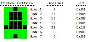
Now we get the values for each row as shown.

  Bit:     4 3 2 1 0 - Hex
  Row1: 0 0 1 0 0 - 0x04
  Row2: 0 1 1 1 0 - 0x0E
  Row3: 0 1 1 1 0 - 0x0E
  Row4: 0 1 1 1 0 - 0x0E
  Row5: 1 1 1 1 1 - 0x1F
  Row6: 0 0 0 0 0 - 0x00
  Row7: 0 0 1 0 0 - 0x04
  Row8: 0 0 0 0 0 - 0x00

We are not using row 8 as in our pattern it is not required. if you are using cursor then it is recommended not to use the 8th row. Now as we have got the values. We just need to put these values in the CGRAM. You can decided which place you want to store in. Following is the memory map for custom patterns in CGRAM.

Memory Map
Pattern No.CGRAM Address (Acg)
10x00 - 0x07
20x08 - 0x0F
30x10 - 0x17
40x18 - 0x1F
50x20 - 0x27
60x28 - 0x2F
70x30 - 0x37
80x38 - 0x3F

We can point the cursor to CGRAM address by sending command, which is 0x40 + CGRAM address (For more information please see Table 4 in commands section). Lets say we want to write the Bell pattern at second pattern location. So we send the command as 0x48 (0x40 + 0x08), and then we send the pattern data. Below is a small programming example to do this.

CODE:
;LCD Ports are same as discussed in previous sections

LCD_build:
         mov   A,#48H         ;Load the location where we want to store
         acall LCD_command    ;Send the command
         mov   A,#04H         ;Load row 1 data
         acall LCD_senddata   ;Send the data
         mov   A,#0EH         ;Load row 2 data
         acall LCD_senddata   ;Send the data
         mov   A,#0EH         ;Load row 3 data
         acall LCD_senddata   ;Send the data
         mov   A,#0EH         ;Load row 4 data
         acall LCD_senddata   ;Send the data
         mov   A,#1FH         ;Load row 5 data
         acall LCD_senddata   ;Send the data
         mov   A,#00H         ;Load row 6 data
         acall LCD_senddata   ;Send the data
         mov   A,#04H         ;Load row 7 data
         acall LCD_senddata   ;Send the data
         mov   A,#00H         ;Load row 8 data
         acall LCD_senddata   ;Send the data
         ret                  ;Return from routine

The above routine will create bell character at pattern location 2. To display the above generated pattern on LCD, simply load the pattern location (0,1,2,...7) and call the LCD_senddata subroutine. Now we can also write the above routine in C as...

CODE:
//LCD Ports are same as discussed in previous sections
void LCD_build(){
        LCD_command(0x48);       //Load the location where we want to store
        LCD_senddata(0x04);      //Load row 1 data
        LCD_senddata(0x0E);      //Load row 2 data
        LCD_senddata(0x0E);      //Load row 3 data
        LCD_senddata(0x0E);      //Load row 4 data
        LCD_senddata(0x1F);      //Load row 5 data
        LCD_senddata(0x00);      //Load row 6 data
        LCD_senddata(0x04);      //Load row 7 data
        LCD_senddata(0x00);      //Load row 8 data
}

I think now most of you find programing in C more simple than assembly. We can also summarize the above in a simple small routine so that you can simply call the build routine providing a pointer to array containing the build data. Below example shows how to do it.
CODE:
//Input:
//     location: location where you want to store
//               0,1,2,....7
//     ptr: Pointer to pattern data
//
//Usage:
//     pattern[8]={0x04,0x0E,0x0E,0x0E,0x1F,0x00,0x04,0x00};
//     LCD_build(1,pattern);
//
//LCD Ports are same as discussed in previous sections

void LCD_build(unsigned char location, unsigned char *ptr){
      unsigned char i;
      if(location<8){
          LCD_command(0x40+(location*8));
          for(i=0;i<8;i++)
             LCD_senddata(ptr[ i ]);
     }
}
 

So the above example shows how to simpify most of your work. To make easy for you to find the values for custom patterns. You can make use of Custom Character Calculator given below.

Custom Character Calculator
BitmapDecimalHex

List of bitmap values:
Dec:
Hex:


This part of the tutorial ends here. For programming help please post in the forum. Have a nice time with your LCD.

Friday, January 12, 2007

Sending Commands to LCD

►Sending Commands to LCD

To send commands we simply need to select the command register. Everything is same as we have done in the initialization routine. But we will summarize the common steps and put them in a single subroutine. Following are the steps:
  • Move data to LCD port
  • select command register
  • select write operation
  • send enable signal
  • wait for LCD to process the command

Keeping these steps in mind we can write LCD command routine as.


CODE:
;Ports used are same as the previous example
;Routine to send command to LCD

LCD_command:
         mov   LCD_data,A     ;Move the command to LCD port
         clr   LCD_rs         ;Selected command register
         clr   LCD_rw         ;We are writing in instruction register
         setb  LCD_en         ;Enable H->L
         clr   LCD_en
         acall LCD_busy       ;Wait for LCD to process the command
         ret                  ;Return from busy routine

; Usage of the above routine
; A will carry the command for LCD
; e.g. we want to send clear LCD command
;
; mov   a,#01H         ;01H is command for clearing LCD
; acall LCD_command    ;Send the command


The equivalent C code Keil C compiler. Similar code can be written for SDCC.

CODE:
void LCD_command(unsigned char var)
{
     LCD_data = var;      //Function set: 2 Line, 8-bit, 5x7 dots
     LCD_rs   = 0;        //Selected command register
     LCD_rw   = 0;        //We are writing in instruction register
     LCD_en   = 1;        //Enable H->L
     LCD_en   = 0;
     LCD_busy();          //Wait for LCD to process the command
}
// Using the above function is really simple
// var will carry the command for LCD
// e.g.
//
// LCD_command(0x01);


Setting cursor position on LCD
To set the cursor position on LCD, we need to send the DDRAM address...
CODE:
Bit7  6   5   4   3   2   1   0
 1   AD6 AD5 AD4 AD3 AD2 AD1 AD0


The seventh bit is always 1, and bit 0 to 7 are DDRAM address (See the introduction section of LCD). so if you want to put the cursor on first position the address will be '0000000B' in binary and 7th bit is 1. so address will be 0x80, so for DDRAM all address starts from 0x80.

For 2 line and 16 character LCD. The adress from 0x80 to 0x8F are visible on first line and 0xC0 to 0xCF is visible on second line, rest of the DDRAM area is still available but is not visible on the LCD, if you want to check this thing, then simply put a long sting greater than 16 character and shift the entire display, you will see all the missing character coming from the back.. this way you can make scrolling line on LCD (see more on shifting display in commands section).

Below is an example for setting cursor position on LCD.

CODE:
;We are placing the cursor on the 4th position
;so the DDRAM address will be 0x03
;and the command will be 0x80+0x03 = 0x83
mov a,#83H           ;load the command
acall LCD_command    ;send command to LCD


CODE:
// to do the same thing is C
// as we done before
LCD_command(0x83);


►Sending Data to LCD

To send data we simply need to select the data register. Everything is same as the command routine. Following are the steps:
  • Move data to LCD port
  • select data register
  • select write operation
  • send enable signal
  • wait for LCD to process the data

Keeping these steps in mind we can write LCD command routine as.


CODE:
;Ports used are same as the previous example
;Routine to send data (single character) to LCD

LCD_senddata:
         mov   LCD_data,A     ;Move the command to LCD port
         setb  LCD_rs         ;Selected data register
         clr   LCD_rw         ;We are writing
         setb  LCD_en         ;Enable H->L
         clr   LCD_en
         acall LCD_busy       ;Wait for LCD to process the data
         ret                  ;Return from busy routine

; Usage of the above routine
; A will carry the character to display on LCD
; e.g. we want to print A on LCD
;
; mov   a,#'A'         ;Ascii value of 'A' will be loaded in accumulator
; acall LCD_senddata   ;Send data


The equivalent C code Keil C compiler. Similar code can be written for SDCC.

CODE:
void LCD_senddata(unsigned char var)
{
     LCD_data = var;      //Function set: 2 Line, 8-bit, 5x7 dots
     LCD_rs   = 1;        //Selected data register
     LCD_rw   = 0;        //We are writing
     LCD_en   = 1;        //Enable H->L
     LCD_en   = 0;
     LCD_busy();          //Wait for LCD to process the command
}
// Using the above function is really simple
// we will pass the character to display as argument to function
// e.g.
//
// LCD_senddata('A');


Now you have seen that its really easy to send command and data to LCD. Now what if we have a string to send to LCD? how we are going to do that?

Is simple, we will store the LCD string in the ROM of controller and call the string character by character. A simple exmple is shown below.


CODE:
;Sending string to LCD Example

LCD_sendstring:
         clr   a                 ;clear Accumulator for any previous data
         movc  a,@a+dptr         ;load the first character in accumulator
         jz    exit              ;go to exit if zero
         acall lcd_senddata      ;send first char
         inc   dptr              ;increment data pointer
         sjmp  LCD_sendstring    ;jump back to send the next character
exit:
         ret                     ;End of routine

; Usage of the above routine
; DPTR(data pointer) will carry the address
; of string to send to LCD.
; e.g. we want to print "LCD Tutorial" on LCD then
;
; mov   dptr,#my_string   ;my_string is the label where the string is stored
; acall LCD_sendstring    ;Send string
;
; To store a string..
; my_string:
; DB   "LCD Tutorial", 00H
; 00H indicate that string is finished.


The equivalent C code Keil C compiler. Similar code can be written for SDCC.

CODE:
void LCD_sendstring(unsigned char *var)
{
     while(*var)              //till string ends
       LCD_senddata(*var++);  //send characters one by one
}
// Using the above function is really simple
// we will pass the string directly to the function
// e.g.
//
// LCD_sendstring("LCD Tutorial");


Now we are ready with sending data and sending command to LCD. Now the last and final section which is creating custom characters or patterns to display on LCD. Please proceed to the next section to read more.

Wednesday, January 10, 2007

Reading the busy Flag

►Reading the busy Flag

As discussed in the previous section, there must be some delay which is needed to be there for LCD to successfully process the command or data. So this delay can be made either with a delay loop of specified time more than that of LCD process time or we can read the busy flag, which is recomended. The reason to use busy flag is that delay produced is almost for the exact amount of time for which LCD need to process the time. So is best suited for every application.


Steps to read busy flag

when we send the command, the BF or D7th bit of the LCD becomes 1 and as soon as the command is processed the BF = 0. Following are the steps to be kept in mind while reading the Busy flag.
  • Select command register
  • Select read operation
  • Send enable signal
  • Read the flag

So following the above steps we can write the code in assembly as below...


CODE:
;Ports used are same as the previous example

LCD_busy:
         setb   LCD_D7        ;Make D7th bit of LCD data port as i/p
         setb   LCD_en        ;Make port pin as o/p
         clr    LCD_rs        ;Select command register
         setb   LCD_rw        ;we are reading
check:
         clr    LCD_en        ;Enable H->L
         setb   LCD_en
         jb     LCD_D7,check  ;read busy flag again and again till it becomes 0
         ret                  ;Return from busy routine


The equivalent C code Keil C compiler. Similar code can be written for SDCC.

CODE:
void LCD_busy()
{
     LCD_D7   = 1;           //Make D7th bit of LCD as i/p
     LCD_en   = 1;           //Make port pin as o/p
     LCD_rs   = 0;           //Selected command register
     LCD_rw   = 1;           //We are reading
     while(LCD_D7){          //read busy flag again and again till it becomes 0
           LCD_en   = 0;     //Enable H->L
           LCD_en   = 1;
     }
}


The above routine will provide the necessary delay for the instructions to complete. If you dont want to read the busy flag you can simply use a delay routine to provide the a specific ammount of delay. A simple delay routine for the LCD is given below.

CODE:
LCD_busy:
         mov  r7,#50H
back:
         mov  r6,#FFH
         djnz r6,$
         djnz r7,back
         ret                  ;Return from busy routine


CODE:
void LCD_busy()
{
         unsigned char i,j;
         for(i=0;i<50;i++)        //A simple for loop for delay
            for(j=0;j<255;j++);
}

Now we are ready with the initialization routine and the busy routine for LCD. In the next section we will see how to send data and command to the LCD.

Monday, January 08, 2007

LCD Initialization

►LCD Initialization

Before using the LCD for display purpose, LCD has to be initialized either by the internal reset circuit or sending set of commands to initialize the LCD. It is the user who has to decide whether an LCD has to be initialized by instructions or by internal reset circuit. we will dicuss both ways of initialization one by one.


Initialization by internal Reset Circuit

An internal reset circuit automatically initializes the HD44780U when the power is turned on. The following instructions are executed during the initialization. The busy flag (BF) is kept in the busy state until the initialization ends (BF = 1). The busy state lasts for 10 ms after VCC rises to 4.5 V.
  • Display clear
  • Function set:
    DL = 1; 8-bit interface data
    N = 0; 1-line display
    F = 0; 5 x 8 dot character font
  • Display on/off control:
    D = 0; Display off
    C = 0; Cursor off
    B = 0; Blinking off
  • Entry mode set:
    I/D = 1; Increment by 1
    S = 0; No shift

Note: If the electrical characteristics conditions listed under the table Power Supply Conditions Using Internal Reset Circuit are not met, the internal reset circuit will not operate normally and will fail to initialize the HD44780U. For such a case, initial-ization must be performed by the MCU as explained in the section, Initializing by Instruction.


As mentioned in the Note, there are certain condtions that has to be met, if user want to use initialization by internal reset circuit. These conditions are shown in the Table 5 below.

Power supply condition for internal reset circuit
Table 5: Power Supply condition for Internal Reset circuit

Figure 7 shows the test condition which are to be met for internal reset circuit to be active.
Internal power supply reset
Figure 7: Internal Power Supply reset


Now the problem with the internal reset circuit is, it is highly dependent on power supply, to meet this critical power supply conditions is not hard but are difficult to achive when you are making a simple application. So usually the second menthod i.e. Initialization by instruction is used and is recommended most of the time.


Initialization by instructions

Initializing LCD with instructions is really simple. Given below is a flowchart that describles the step to follow, to initialize the LCD.
LCD initialization flow chart
Figure 8: Flow chart for LCD initialization

As you can see from the flow chart, the LCD is initialized in the following sequence...
1) Send command 0x30 - Using 8-bit interface
2) Delay 20ms
3) Send command 0x30 - 8-bit interface
4) Delay 20ms
5) Send command 0x30 - 8-bit interface
6) Delay 20ms
7) Send Function set - see Table 4 for more information
8) Display Clear command
9) Set entry mode command - explained below

The first 3 commands are usually not required but are recomended when you are using 4-bit interface. So you can program the LCD starting from step 7 when working with 8-bit interface. Function set command depends on what kind of LCD you are using and what kind of interface you are using (see Table 4 in LCD Command section).

LCD Entry mode
From Table 3 in command section, you can see that the two bits decide the entry mode for LCD, these bits are:
a) I/D - Increment/Decrement bit
b) S - Display shift.
With these two bits we get four combinations of entry mode which are 0x04,0x05,0x06,0x07 (see table 3 in LCD Command section). So we get different results with these different entry modes. Normally entry mode 0x06 is used which is No shift and auto incremement. I recommend you to try all the possible entry modes and see the results, I am sure you will be surprised.


Programming example for LCD Initialization

CODE:
LCD_data equ P2    ;LCD Data port
LCD_D7   equ P2.7  ;LCD D7/Busy Flag
LCD_rs   equ P1.0  ;LCD Register Select
LCD_rw   equ P1.1  ;LCD Read/Write
LCD_en   equ P1.2  ;LCD Enable

LCD_init:
         mov   LCD_data,#38H  ;Function set: 2 Line, 8-bit, 5x7 dots
         clr   LCD_rs         ;Selected command register
         clr   LCD_rw         ;We are writing in instruction register
         setb  LCD_en         ;Enable H->L
         clr   LCD_en
         acall LCD_busy       ;Wait for LCD to process the command
         mov   LCD_data,#0FH  ;Display on, Curson blinking command
         clr   LCD_rs         ;Selected instruction register
         clr   LCD_rw         ;We are writing in instruction register
         setb  LCD_en         ;Enable H->L
         clr   LCD_en
         acall LCD_busy       ;Wait for LCD to process the command
         mov   LCD_data,#01H  ;Clear LCD
         clr   LCD_rs         ;Selected command register
         clr   LCD_rw         ;We are writing in instruction register
         setb  LCD_en         ;Enable H->L
         clr   LCD_en
         acall LCD_busy       ;Wait for LCD to process the command
         mov   LCD_data,#06H  ;Entry mode, auto increment with no shift
         clr   LCD_rs         ;Selected command register
         clr   LCD_rw         ;We are writing in instruction register
         setb  LCD_en         ;Enable H->L
         clr   LCD_en
         acall LCD_busy       ;Wait for LCD to process the command
         ret                  ;Return from routine


Now we can do the same thing in C, I am giving example using Keil C. Similar code can be written for SDCC.
CODE:
#include <AT89X51.H>.
#define LCD_data P2
#define LCD_D7   P2_7
#define LCD_rs   P1_0
#define LCD_rw   P1_1
#define LCD_en   P1_2

void LCD_init()
{
     LCD_data = 0x38;     //Function set: 2 Line, 8-bit, 5x7 dots
     LCD_rs   = 0;        //Selected command register
     LCD_rw   = 0;        //We are writing in data register
     LCD_en   = 1;        //Enable H->L
     LCD_en   = 0;
     LCD_busy();          //Wait for LCD to process the command
     LCD_data = 0x0F;     //Display on, Curson blinking command
     LCD_rs   = 0;        //Selected command register
     LCD_rw   = 0;        //We are writing in data register
     LCD_en   = 1;        //Enable H->L
     LCD_en   = 0;
     LCD_busy();          //Wait for LCD to process the command
     LCD_data = 0x01;     //Clear LCD
     LCD_rs   = 0;        //Selected command register
     LCD_rw   = 0;        //We are writing in data register
     LCD_en   = 1;        //Enable H->L
     LCD_en   = 0;
     LCD_busy();          //Wait for LCD to process the command
     LCD_data = 0x06;     //Entry mode, auto increment with no shift
     LCD_rs   = 0;        //Selected command register
     LCD_rw   = 0;        //We are writing in data register
     LCD_en   = 1;        //Enable H->L
     LCD_busy();
}


With the help of the above code, you are able to initialize the LCD. Now there is a function/subroutine coming in the code i.e. LCD_busy, which is used to put delay for LCD so that there should not be any command or data sent to the LCD untill it finish executing the command. More on this delay routine is explained in the next section.

Friday, January 05, 2007

Commands and Instruction set

►Commands and Instruction set

Only the instruction register (IR) and the data register (DR) of the LCD can be controlled by the MCU. Before starting the internal operation of the LCD, control information is temporarily stored into these registers to allow interfacing with various MCUs, which operate at different speeds, or various peripheral control devices. The internal operation of the LCD is determined by signals sent from the MCU. These signals, which include register selection signal (RS), read/write signal (R/W), and the data bus (DB0 to DB7), make up the LCD instructions (Table 3). There are four categories of instructions that:

  • Designate LCD functions, such as display format, data length, etc.
  • Set internal RAM addresses
  • Perform data transfer with internal RAM
  • Perform miscellaneous functions


LCD type HD44780 command and instruction set
Table 3: Command and Instruction set for LCD type HD44780


Although looking at the table you can make your own commands and test them. Below is a breif list of useful commands which are used frequently while working on the LCD.


No. InstructionHexDecimal
1 Function Set: 8-bit, 1 Line, 5x7 Dots 0x3048
2 Function Set: 8-bit, 2 Line, 5x7 Dots 0x3856
3 Function Set: 4-bit, 1 Line, 5x7 Dots 0x2032
4 Function Set: 4-bit, 2 Line, 5x7 Dots 0x2840
5Entry Mode0x066
6 Display off Cursor off
(clearing display without clearing DDRAM content)
0x088
7 Display on Cursor on 0x0E14
8 Display on Cursor off 0x0C12
9 Display on Cursor blinking 0x0F15
10 Shift entire display left 0x1824
12 Shift entire display right 0x1C30
13 Move cursor left by one character 0x10 16
14 Move cursor right by one character 0x1420
15 Clear Display (also clear DDRAM content)0x011
16 Set DDRAM address or coursor position on display 0x80+add* 128+add*
17 Set CGRAM address or set pointer to CGRAM location0x40+add**64+add**
Table 4: Frequently used commands and instructions for LCD

* DDRAM address given in LCD basics section see Figure 2,3,4
** CGRAM address from 0x00 to 0x3F, 0x00 to 0x07 for char1 and so on..

The table above will help you while writing programs for LCD. But after you are done testing with the table 4, i recommend you to use table 3 to get more grip on working with LCD and trying your own commands. In the next section of the tutorial we will see the initialization with some of the coding examples in C as well as assembly.

Wednesday, January 03, 2007

Memory

►DDRAM - Display Data RAM

Display data RAM (DDRAM) stores display data represented in 8-bit character codes. Its extended capacity is 80 X 8 bits, or 80 characters. The area in display data RAM (DDRAM) that is not used for display can be used as general data RAM. So whatever you send on the DDRAM is actually displayed on the LCD. For LCDs like 1x16, only 16 characters are visible, so whatever you write after 16 chars is written in DDRAM but is not visible to the user.

Figures below will show you the DDRAM addresses of 1 Line, 2 Line and 4 Line LCDs.


1 Line LCD DDRAM address
Figure 2: DDRAM Address for 1 Line LCD

2 Line LCD DDRAM address
Figure 3: DDRAM Address for 2 Line LCD

4 Line LCD DDRAM address
Figure 4: DDRAM Address for 4 Line LCD


►CGROM - Character Generator ROM

Now you might be thinking that when you send an ascii value to DDRAM, how the character is displayed on LCD? so the answer is CGROM. The character generator ROM generates 5 x 8 dot or 5 x 10 dot character patterns from 8-bit character codes (see Figure 5 and Figure 6 for more details). It can generate 208 5 x 8 dot character patterns and 32 5 x 10 dot character patterns. Userdefined character patterns are also available by mask-programmed ROM.
LCD characters code map for 5x8 dots
Figure 5: LCD characters code map for 5x8 dots

LCD characters code map for 5x10 dots
Figure 6: LCD characters code map for 5x10 dots
As you can see in both the code maps, the character code from 0x00 to 0x07 is occupied by the CGRAM characters or the user defined characters. If user want to display the fourth custom character then the code to display it is 0x03 i.e. when user send 0x03 code to the LCD DDRAM then the fourth user created charater or patteren will be displayed on the LCD.


►CGRAM - Character Generator RAM

As clear from the name, CGRAM area is used to create custom characters in LCD. In the character generator RAM, the user can rewrite character patterns by program. For 5 x 8 dots, eight character patterns can be written, and for 5 x 10 dots, four character patterns can be written. Later in this tutorial i will explain how to use CGRAM area to make custom character and also making animations to give nice effects to your application.


►BF - Busy Flag

Busy Flag is an status indicator flag for LCD. When we send a command or data to the LCD for processing, this flag is set (i.e BF =1) and as soon as the instruction is executed successfully this flag is cleared (BF = 0). This is helpful in producing and exact ammount of delay. for the LCD processing.

To read Busy Flag, the condition RS = 0 and R/W = 1 must be met and The MSB of the LCD data bus (D7) act as busy flag. When BF = 1 means LCD is busy and will not accept next command or data and BF = 0 means LCD is ready for the next command or data to process.


►Instruction Register (IR) and Data Register (DR)

There are two 8-bit registers in HD44780 controller Instruction and Data register. Instruction register corresponds to the register where you send commands to LCD e.g LCD shift command, LCD clear, LCD address etc. and Data register is used for storing data which is to be displayed on LCD. when send the enable signal of the LCD is asserted, the data on the pins is latched in to the data register and data is then moved automatically to the DDRAM and hence is displayed on the LCD.
Data Register is not only used for sending data to DDRAM but also for CGRAM, the address where you want to send the data, is decided by the instruction you send to LCD. We will discuss more on LCD instuction set further in this tutorial.