Introduction
The most commonly used Character based LCDs are based on Hitachi's
HD44780 controller or other which are compatible with HD44580. In this
tutorial, we will discuss about character based LCDs, their interfacing
with various microcontrollers, various interfaces (8-bit/4-bit),
programming, special stuff and tricks you can do with these simple
looking LCDs which can give a new look to your application.For Specs and technical information HD44780 controller Click Here
Pin Description
The most commonly used LCDs found in the market today are 1 Line, 2 Line or 4 Line LCDs which have only 1 controller and support at most of 80 charachers, whereas LCDs supporting more than 80 characters make use of 2 HD44780 controllers.
Most LCDs with 1 controller has 14 Pins and LCDs with 2 controller has 16 Pins (two pins are extra in both for back-light LED connections). Pin description is shown in the table below.
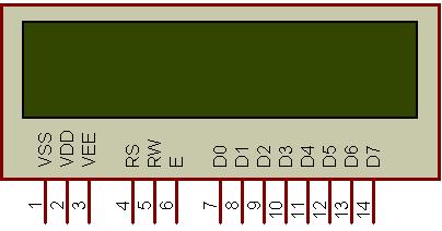
Figure 1: Character LCD type HD44780 Pin diagram
| Pin No. | Name | Description |
| Pin no. 1 | VSS | Power supply (GND) |
| Pin no. 2 | VCC | Power supply (+5V) |
| Pin no. 3 | VEE | Contrast adjust |
| Pin no. 4 | RS | 0 = Instruction input 1 = Data input |
| Pin no. 5 | R/W | 0 = Write to LCD module 1 = Read from LCD module |
| Pin no. 6 | EN | Enable signal |
| Pin no. 7 | D0 | Data bus line 0 (LSB) |
| Pin no. 8 | D1 | Data bus line 1 |
| Pin no. 9 | D2 | Data bus line 2 |
| Pin no. 10 | D3 | Data bus line 3 |
| Pin no. 11 | D4 | Data bus line 4 |
| Pin no. 12 | D5 | Data bus line 5 |
| Pin no. 13 | D6 | Data bus line 6 |
| Pin no. 14 | D7 | Data bus line 7 (MSB) |
| Pin No. | Name | Description |
| Pin no. 1 | D7 | Data bus line 7 (MSB) |
| Pin no. 2 | D6 | Data bus line 6 |
| Pin no. 3 | D5 | Data bus line 5 |
| Pin no. 4 | D4 | Data bus line 4 |
| Pin no. 5 | D3 | Data bus line 3 |
| Pin no. 6 | D2 | Data bus line 2 |
| Pin no. 7 | D1 | Data bus line 1 |
| Pin no. 8 | D0 | Data bus line 0 (LSB) |
| Pin no. 9 | EN1 | Enable signal for row 0 and 1 (1stcontroller) |
| Pin no. 10 | R/W | 0 = Write to LCD module 1 = Read from LCD module |
| Pin no. 11 | RS | 0 = Instruction input 1 = Data input |
| Pin no. 12 | VEE | Contrast adjust |
| Pin no. 13 | VSS | Power supply (GND) |
| Pin no. 14 | VCC | Power supply (+5V) |
| Pin no. 15 | EN2 | Enable signal for row 2 and 3 (2ndcontroller) |
| Pin no. 16 | NC | Not Connected |